Modul 3 SPI
3:06:00 PM
B. KOMUNIKASI SPI
1. Hardware [kembali]

Push Button

LED


Power Supply
2. Rangkaian Simulasi [kembali]

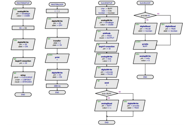
3. Listing Program [kembali]
//MASTER
#include <SPI.h> //Deklarasi library SPI
void setup (void) {
Serial.begin(115200); //Set baud rate 115200
digitalWrite(SS, HIGH);
// disable Slave Select
SPI.begin ();
SPI.setClockDivider(SPI_CLOCK_DIV8); //divide the clock by 8
}
void loop (void) {
char c;
digitalWrite(SS, LOW); //enable Slave Select
// send test string
for (const char * p = "Hello,
world!\r" ; c = *p; p++)
{
SPI.transfer (c);
Serial.print(c);
}
digitalWrite(SS, HIGH); // disable Slave
Select
delay(2000);
}
//SLAVE
#include <SPI.h>
char buff [50];
volatile byte indx;
volatile boolean process;
void setup (void) {
Serial.begin (115200);
pinMode(MISO, OUTPUT); // have to send on
master in so it set as output
SPCR |= _BV(SPE); // turn on SPI in slave
mode
indx = 0; // buffer empty
process = false;
SPI.attachInterrupt(); // turn on interrupt
}
ISR (SPI_STC_vect)
// SPI interrupt routine
{
byte c = SPDR; // read byte from SPI Data
Register
if (indx < sizeof buff) {
buff [indx++] = c; // save data in the next
index in the array buff
if (c == '\r') //check for the end of the
word
process = true;
}
}
void loop (void) {
if (process) {
process = false; //reset the process
Serial.println (buff); //print the array on
serial monitor
indx = 0; //reset button to zero
}
}
Visual Designer
File Proteus - Download
File Program - Download
Video Rangkaian - Download
Datasheet LED - Download
Datasheet Push Button - Download
Datasheet Arduino Uno - Download


